For over 30 years, PTC has set the standard in CAD software for parametric modeling, simulation and analysis, and product documentation. Whether you need robust on‑premises tools or modern SaaS, our computer aided design solutions help teams accelerate innovation, improve quality, and get products to market faster.
What Is CAD? (CAD Full Form: Computer Aided Design)
-
CAD full form: computer aided design.
-
What is CAD? CAD is the use of specialized software to create precise 2D drawings and realistic 3D models of products before manufacturing. With 3D design, engineers and designers can share, review, simulate, and iterate quickly-reducing errors and enabling faster, higher‑quality outcomes.
-
What is CAD design? CAD design refers to the process of modeling parts, assemblies, and documentation digitally to validate form, fit, and function early in the development cycle.
A Brief History of CAD at PTC
In 1985, Dr. Samuel Geisberg founded Parametric Technology Corporation (PTC) and pioneered parametric, feature‑based solid modeling—technology that became Creo, a leading CAD software platform for product design and development. Today, organizations continue to adopt next‑generation capabilities like AI, generative design, and integrated simulation.
What Is a CAD Drawing?
A CAD drawing is a detailed digital plan of an object, structure, or system created with cad software. Used across architecture, engineering, and manufacturing, CAD drawings streamline documentation, improve accuracy, and connect design to downstream production.
Benefits of CAD Software
-
Reduce time to market: Increase engineering productivity with rapid updates and change management in cad design workflows while reducing errors.
-
Enhance documentation and communication: Generate accurate, model‑based documentation directly from your 3D design to align teams and stakeholders.
-
Increase product development efficiency: Explore alternatives quickly, identify issues early, and cut rework and cost.
-
Streamline manufacturing: Send CAD and CAM data directly to machining and production systems for a seamless handoff.
-
Accelerate high‑quality innovation: Improve precision and product performance using integrated simulation and analysis.
AI in CAD
Artificial intelligence is transforming computer aided design by:
-
Automating repetitive tasks and model cleanup
-
Generating and optimizing design alternatives (generative design)
-
Predicting issues earlier with data‑driven insights
-
Running rapid simulations to validate performance
The result: faster cycles, fewer prototypes, lower costs, and better outcomes in cad design.
What Is CAM? (CAM Full Form: Computer Aided Manufacturing)
-
CAM full form: computer aided manufacturing.
-
CAM works alongside CAD to automate and optimize manufacturing processes. CAM software turns CAD models into toolpaths and machine instructions, improving precision, reducing human error, and accelerating production. CAD + CAM integration enables a continuous digital thread from design to manufacturing.
CAD Software Capabilities in Creo
-
2D drawings: Clear blueprints that communicate design intent and drive downstream work.
-
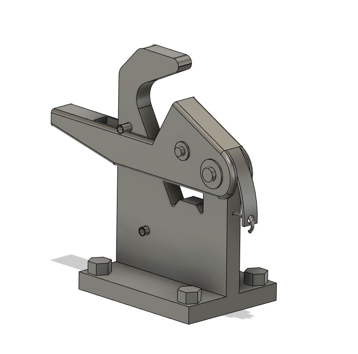
3D design: High‑fidelity part and assembly modeling for accurate visualization and validation.
-
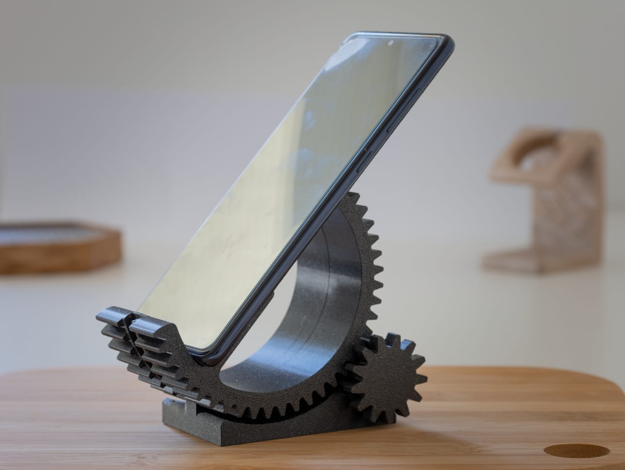
Additive manufacturing (AM): Design for 3D printing, optimize lattices and structures, and prepare builds to reduce cost and weight.
-
Assembly drawings: Technical illustrations with dimensions, materials, and specifications.
-
Assembly modeling: Validate fit, motion, and function before physical prototyping.
-
CAM software: Generate precise, efficient toolpaths directly from CAD models.
-
Composite part design and manufacturing: Engineer layups to achieve superior, tailored properties.
-
Computer‑aided engineering (CAE): Simulate performance, reliability, and safety to optimize early.
-
Concept design: Rapidly transform ideas into visual models aligned with user needs.
-
Generative design: Input goals and constraints; software proposes efficient, innovative geometries.
-
Geometric dimensioning and tolerancing (GD&T): Communicate tolerances consistently with standardized symbols.
-
Model‑based definition (MBD): Embed dimensions and annotations in the 3D model as the single source of truth.
-
Model‑based enterprise (MBE): Extend the model to manufacturing, quality, and service for faster, consistent workflows.
-
MultiCAD: Collaborate across multiple CAD systems without translation bottlenecks.
-
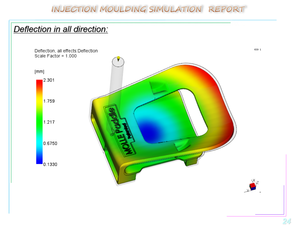
Simulation and analysis: Validate real‑world loads and conditions on virtual prototypes.
Why Choose PTC for CAD and CAM?
-
Proven innovation: Decades of leadership in parametric modeling and digital transformation.
-
Flexibility: Choice of on‑prem or SaaS cad software to match your IT strategy.
-
Depth and breadth: From concept and 3D design to CAM, CAE, AM, and MBD/MBE.
-
Integrated workflows: A connected toolchain that reduces friction from design to production.
FAQs: CAD, CAM, and 3D Design
-
What is CAD?
-
CAD stands for computer aided design-software used to create precise 2D drawings and 3D models before manufacturing.
-
What is CAD design?
-
The process of creating and validating digital models (parts, assemblies, and documentation) to ensure form, fit, and function.
-
What is CAM?
-
CAM stands for computer aided manufacturing-software that converts CAD data into machine instructions for manufacturing.
-
How do CAD and CAM work together?
-
CAD defines the product; CAM defines how to make it. Integrated CAD/CAM shortens lead times and reduces errors.
-
Which industries use CAD software?
-
Automotive, aerospace, industrial equipment, consumer products, medical devices, AEC, and more.